One of the most exciting features of EVPN technology is support for L2 Multi-Homing, where customer CE/Server/VM can be connected to multiple PE devices as depicted below.
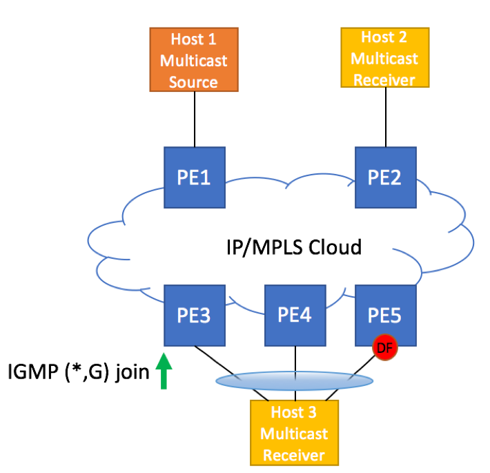
While providing many advantages, site Multi-Homing can pose some challenges when it comes to Multicast behavior.
In All-Active Multi-homing scenario depicted above, there is no guarantee that IGMP Join / Leave packets will be sent to Designated Forwarder (DF) router for the segment.
In fact, depending on Host 3’s hashing algorithm, IGMP joins might be sent to PE3, PE4 or PE5. It is also possible that IGMP joins for different multicast groups will be sent to different PEs.
Furthermore, IGMP Leave Message for a given group might not be sent to the same PE as IGMP Join message.
Single-Active redundancy mode suffers from similar behavior. Unless IGMP state is synchronized across all Ethernet Segment (ES)-servicing nodes, failover from one PE to another will lead to lost IGMP state on a node that just became active.
Thus, there is a need for IGMP synchronization mechanism that would allow all PE devices serving given ES to share their state. This is done by leveraging EVPN Type 7 (IGMP Join Synch Route) and Type 8 (IGMP Leave Synch Route) routes.
PE devices not serving given ES will ignore these routes.
Type 7 (IGMP Join Synch Route) Format
Type 7 message is shown below:
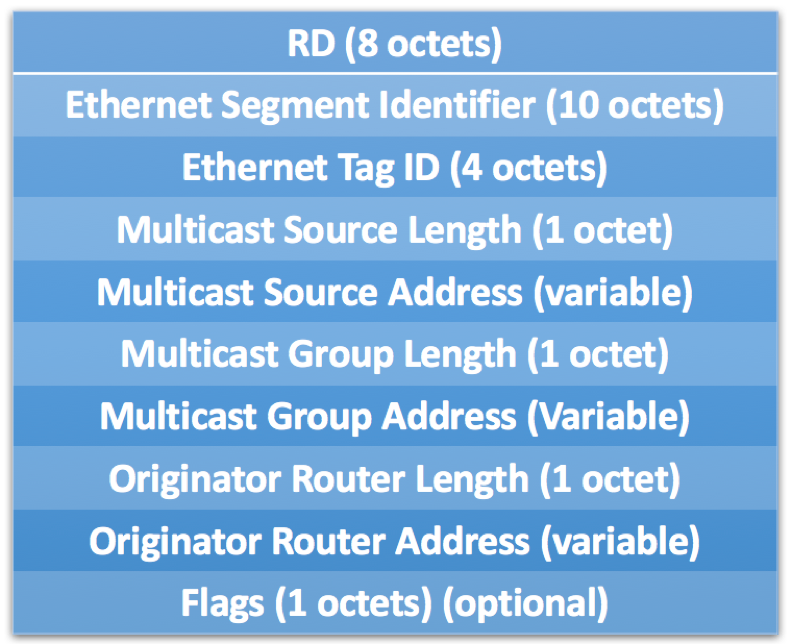
The Ethernet Segment Identifier (ESI) MUST be set to the 10-octet value defined for the ES.
Ethernet Tag ID must be set to the following values
- Zero if EVI is VLAN-Based or VLAN Bundle service
- Customer VID for the [EVI, BD ] if EVI is VLAN-Aware Bundle service without translation
- Normalized Ethernet Tag ID for the [EVI, BD] if EVI is VLAN-Aware Bundle service with translation.
The Flag field is issued to communicate IGMP version information and is defined as follows:
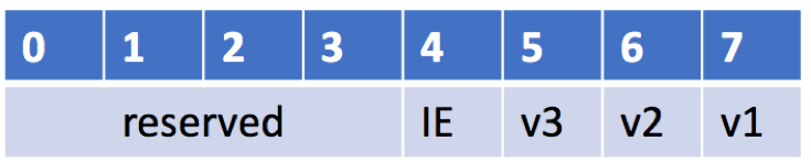
Bit 4 (IE) is Include Group type (bit value 0) or an Exclude Group type (bit value 1) and is ignored if bit 5 (IGMPv3) is not set.
Type 8 (IGMP Leave Synch Route) Format
Type 8 message is shown below:
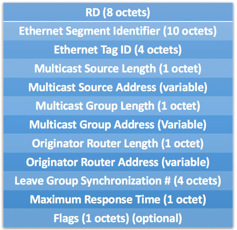
There are two new fields that were not present in IGMP Join Packets.
Leave Group Synchronization Number – identifies the specific (x, G) leave group synchronization procedure initiated by the advertising PE, which increments the value whenever it initiates a procedure.
Maximum Response Time – duration of (x, G) leave group synchronization procedure.