Discussion on how to migrate to BGP-Free Core by deploying MPLS as network tunneling mechanism. Document provides step-by-step migration steps for a Juniper-based network.
Introduction
In today’s article, we will discuss how to migrate from BGP-enabled environment to MPLS BGP-Free core. By doing so, you will get yourself ready to provide new services to your customers, such as MPLS VPN, VPLS, IPv6, EVPN, etc.
Please refer to ‘BGP Free Core’ article for more information.
Initial Stage
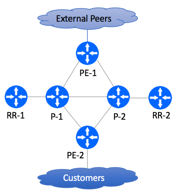
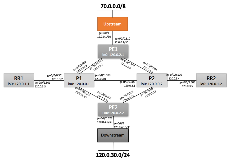
Our environment is comprised of two P nodes, two PE nodes, two Route-Reflectors, external peers and customers. Obviously, your production network will have many more network elements, but the basic principles described in this article should be applicable to a network of any size.
In our setup, we are running IS-IS as our IGP protocol. If you are more familiar with OSPF, you are welcome to run it instead. Before planning the migration, it is recommended to clean up your IGP (OSPF or IS-IS) and BGP domains. All customer routes should be carried in BGP, while all infrastructure routes must be carried in IGP.
Pre-Migration Configuration Elements
IGP Protocol
IS-IS is used as the IGP Protocol. Single L2 Area is configured on all P, PE and Route-Reflectors. There is no route summarization of any kind. All infrastructure routes (loopback and internal point-to-points) are carried over IGP.
PE-1 Configuration Snippet:
PE1> show configuration protocols isis | display set |no-more

set protocols isis level 1 disable
set protocols isis level 2 wide-metrics-only
set protocols isis interface ge-0/0/0.502 point-to-point
set protocols isis interface ge-0/0/0.504 point-to-point
set protocols isis interface lo0.0
BGP Protocol
BGP is configured on all P and PE devices. All customer routes, including customer point-to-points are carried over BGP.
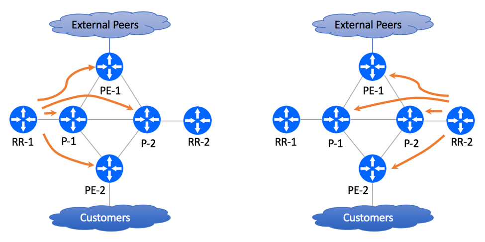
P and PE devices do not have direct IBGP sessions, but peer with two dedicated Router Reflectors.
PE-1 Configuration Snippet:
PE1> show configuration protocols isis | display set |no-more


set protocols bgp group IBGP-RR type internal
set protocols bgp group IBGP-RR local-address 120.0.2.1
set protocols bgp group IBGP-RR family inet unicast
set protocols bgp group IBGP-RR authentication-key "$9$5znCO1hKMXtuMX7-2gTz3"
set protocols bgp group IBGP-RR export NHSelf
set protocols bgp group IBGP-RR neighbor 120.0.1.1
set protocols bgp group IBGP-RR neighbor 120.0.1.2


set protocols bgp group EBGP-Transit type external
set protocols bgp group EBGP-Transit description "Upstream Peering"
set protocols bgp group EBGP-Transit import Transit-In
set protocols bgp group EBGP-Transit family inet unicast prefix-limit maximum 800000
set protocols bgp group EBGP-Transit family inet unicast prefix-limit teardown 80
set protocols bgp group EBGP-Transit family inet unicast prefix-limit teardown idle-timeout 60
set protocols bgp group EBGP-Transit export StaticToEBGP
set protocols bgp group EBGP-Transit export Transit-Out
set protocols bgp group EBGP-Transit neighbor 12.0.0.1 description "Upstream ABC: Circuit A1B2C3: NOC 701-456-8990"
set protocols bgp group EBGP-Transit neighbor 12.0.0.1 authentication-key "$9$QYgH3/t1RSM87uO87-V4oz36"
set protocols bgp group EBGP-Transit neighbor 12.0.0.1 peer-as 701
P-1 Configuration Snippet:
P1> show configuration protocols isis | display set |no-more

set protocols bgp group IBGP-RR type internal
set protocols bgp group IBGP-RR local-address 120.0.0.1
set protocols bgp group IBGP-RR family inet unicast
set protocols bgp group IBGP-RR authentication-key "$9$5znCO1hKMXtuMX7-2gTz3"
set protocols bgp group IBGP-RR neighbor 120.0.1.1
set protocols bgp group IBGP-RR neighbor 120.0.1.2
RR-1 Configuration Snipper:
RR1> show configuration protocols isis | display set |no-more

set protocols bgp group IBGP-PE type internal
set protocols bgp group IBGP-PE local-address 120.0.1.1
set protocols bgp group IBGP-PE family inet unicast
set protocols bgp group IBGP-PE authentication-key "$9$x1N-b2ZUH5Qn4aQn/CB17-V"
set protocols bgp group IBGP-PE cluster 0.0.0.1
set protocols bgp group IBGP-PE neighbor 120.0.2.1
set protocols bgp group IBGP-PE neighbor 120.0.2.2
set protocols bgp group IBGP-PE neighbor 120.0.0.1
set protocols bgp group IBGP-PE neighbor 120.0.0.2
MPLS
Not Configured
LDP
Not Configured
Pre-Migration Network State
Figure below depicts physical network topology.
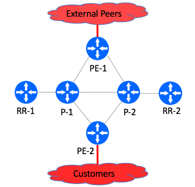
’70.0.0.0/8’ prefix is advertised by the Upstream Peer.
‘120.0.30.0/24’ prefix is advertised by the customer.
During our simulated migration, we will be using these two prefixes to monitor traffic behavior changes.
PE1
PE1> show route 70.0.0.0/8
...
70.0.0.0/8         *[BGP/170] 16:23:56, localpref 40
                      AS path: 701 I, validation-state: unverified
                    > to 12.0.0.1 via ge-0/0/0.510

PE1> show route 120.0.30.0/24
...
120.0.30.0/24      *[BGP/170] 00:11:01, localpref 100, from 120.0.1.1
                      AS path: 65001 I, validation-state: unverified
                    > to 120.0.3.6 via ge-0/0/0.502
                    [BGP/170] 00:00:41, localpref 100, from 120.0.1.2
                      AS path: 65001 I, validation-state: unverified
                    > to 120.0.3.6 via ge-0/0/0.502

PE1> show route 120.0.30.0/24 extensive
…

Path 120.0.30.0 from 120.0.1.1 Vector len 4.  Val: 1 2 3 4
        *BGP    Preference: 170/-101
                Next hop type: Indirect, Next hop index: 0
                Address: 0xb39f430
                Next-hop reference count: 9
                Source: 120.0.1.1
                Next hop type: Router, Next hop index: 584
                Next hop: 120.0.3.6 via ge-0/0/0.502, selected
                Session Id: 0x140
                Protocol next hop: 120.0.2.2
                Indirect next hop: 0xb2b3c90 1048574 INH Session ID: 0x14f
                State: <Active Int Ext>
                Local AS:   100 Peer AS:   100
                …
PE2
PE2> show route 70.0.0.0/8
...
70.0.0.0/8         *[BGP/170] 00:11:36, localpref 40, from 120.0.1.1
                    AS path: 701 I, validation-state: unverified
                    > to 120.0.3.10 via ge-0/0/0.503
                    [BGP/170] 00:01:55, localpref 40, from 120.0.1.2
                    AS path: 701 I, validation-state: unverified
                    > to 120.0.3.10 via ge-0/0/0.503


PE2> show route 70.0.0.0/8 extensive

inet.0: 66 destinations, 72 routes (57 active, 0 holddown, 9 hidden)
70.0.0.0/8 (2 entries, 1 announced)
…
Path 70.0.0.0 from 120.0.1.1 Vector len 4.  Val: 2
        *BGP    Preference: 170/-41
                Next hop type: Indirect, Next hop index: 0
                Address: 0xb39eb90
                Next-hop reference count: 18
                Source: 120.0.1.1
                Next hop type: Router, Next hop index: 578
                Next hop: 120.0.3.10 via ge-0/0/0.503, selected
                Session Id: 0x145
                Protocol next hop: 120.0.2.1
                Indirect next hop: 0xb2b3a70 1048575 INH Session ID: 0x142
                State: <Active Int Ext>
                Local AS:   100 Peer AS:   100

PE2> show route 120.0.30.0/24
...
120.0.30.0/24      *[BGP/170] 16:07:52, localpref 100
                   AS path: 65001 I, validation-state: unverified
                   > to 120.0.4.10 via ge-0/0/0.523

PE2> show route 120.0.30.0/24 extensive | no-more

inet.0: 66 destinations, 72 routes (57 active, 0 holddown, 9 hidden)
120.0.30.0/24 (1 entry, 1 announced)
…
Path 120.0.30.0 from 120.0.4.10 Vector len 4.  Val: 0 2
  *BGP    Preference: 170/-101
    Next hop type: Router, Next hop index: 576
    Address: 0xb39e3b0
    Next-hop reference count: 2
                Source: 120.0.4.10
                Next hop: 120.0.4.10 via ge-0/0/0.523, selected
P1
P1> show route 70.0.0.0/8

inet.0: 30 destinations, 39 routes (30 active, 0 holddown, 0 hidden)
+ = Active Route, - = Last Active, * = Both

70.0.0.0/8         *[BGP/170] 00:10:21, localpref 40, from 120.0.1.1
                   AS path: 701 I, validation-state: unverified
                   > to 120.0.3.7 via ge-0/0/0.502
                   [BGP/170] 00:03:54, localpref 40, from 120.0.1.2
                   AS path: 701 I, validation-state: unverified
                   > to 120.0.3.7 via ge-0/0/0.502
P2
P2> show route 70.0.0.0/8

inet.0: 30 destinations, 39 routes (30 active, 0 holddown, 0 hidden)
+ = Active Route, - = Last Active, * = Both

70.0.0.0/8         *[BGP/170] 00:10:55, localpref 40, from 120.0.1.1
                    AS path: 701 I, validation-state: unverified
                    > to 120.0.3.9 via ge-0/0/0.504
                    [BGP/170] 00:05:13, localpref 40, from 120.0.1.2
                    AS path: 701 I, validation-state: unverified
                    > to 120.0.3.9 via ge-0/0/0.504
Migration Steps
Step 1: Increase Interface MTU
Increase MTU size on all P to P and P to PE links in order to compensate for MPLS header. The actual MTU to be assigned to the interfaces should depend on routers’ interface capabilities and underlying Layer 2 transport. If possible, set the MTU to the maximum size supported by the routers.
If running OSPF, MTU change will trigger OSPF flap. Make sure that you do this during maintenance window.
Don’t forget that MTU change should be done on both sides of the link and MTU settings must match on both sides.
Step 2: Modify RE Protection Filter to allow LDP
You should be using RE Protection Firewall Filter on all your devices in order to protect your infrastructure from external attacks.
set firewall family inet filter accept-protocols term ldp from source-address 120.0.0.0/22

set firewall family inet filter accept-protocols term ldp from protocol tcp

set firewall family inet filter accept-protocols term ldp from protocol udp

set firewall family inet filter accept-protocols term ldp from port ldp

set firewall family inet filter accept-protocols term ldp then accept
Step 3: Enable MPLS and LDP on P-to-P and P-to-PE links
On Juniper routers, you have to configure a few things in order for MPLS and LDP to become operational:
Make sure that the router-id is configured
Loopback address should be used as the router ID
set routing-options router-id 120.0.0.2
Enable MPLS Encapsulation on all transport interfaces
set interfaces ge-0/0/0 unit 502 family mpls
Enable MPLS protocol on transport links.
On P routers, the safest approach is to enable MPLS on all interfaces and explicitly disable MPLS on the interfaces where it is not needed:
set protocols mpls interface all
set protocols mpls interface fxp0.0 disable
On PE routers, enable MPLS on P-facing interfaces:
set protocols mpls interface ge-0/0/0.502
set protocols mpls interface ge-0/0/0.504
set protocols mpls interface lo0.0
Verify that MPLS is enabled on desired interfaces:
> show mpls interface
Interface        State       Administrative groups (x: extended)
ge-0/0/0.502     Up         <none>
ge-0/0/0.504     Up         <none>
Configure LDP Authentication
Create Key-Chain:
set security authentication-key-chains key-chain ldp-chain key 0 secret "$9$32FA/A0EclLxdBIxdbsJZn/C"

set security authentication-key-chains key-chain ldp-chain key 0 start-time "2017-1-1.00:00:00 +0000"
Apply Key-Chain to LDP sessions:
set protocols ldp session-group 120.0.0.0/22 authentication-algorithm aes-128-cmac-96

set protocols ldp session-group 120.0.0.0/22 authentication-key-chain ldp-chain
Specify LDP Transport Address
set protocols ldp transport-address router-id
Enable LDP Protocol
Next step is to start enabling LDP protocol. We recommend Inside-Out approach, where you start with the Core and expand LDP domain to the Edge.
You would leverage the same configuration technique as before.
On P routers, do implicit LDP configuration:
set protocols ldp interface all
set protocols ldp interface fxp0.0 disable
On PE routers, do explicit LDP configuration:
set protocols ldp interface ge-0/0/0.502
set protocols ldp interface ge-0/0/0.504
Configure LDP Synchronization
set protocols ldp igp-synchronization holddown-interval 30
Refer to ‘Understanding LDP-IGP’ Synchronization document if you are not familiar with this feature.
Verify LDP Adjacencies
P1> show ldp neighbor

Address                             Interface       Label space ID     Hold time

120.0.3.1                           ge-0/0/0.500    120.0.0.2:0          11

120.0.3.7                           ge-0/0/0.502    120.0.2.1:0          13

120.0.3.11                          ge-0/0/0.503    120.0.2.2:0          12


P1> show ldp session

Address                           State       Connection  Hold time  Adv. Mode

120.0.0.2                           Operational Open          28         DU

120.0.2.1                           Operational Open          28         DU

120.0.2.2                           Operational Open          28         DU
Make sure all sessions are in ‘Operational’ state.
Traffic Validation
Verify End-to-End Label Switch Paths
At this point of your migration, you have enabled LDP across your P and PE networks.
‘inet.3’ table on all routers should be populated with loopback addresses of your P and PE devices as shown below:
PE1> show route table inet.3


120.0.0.1/32       *[LDP/9] 00:11:46, metric 1
                    > to 120.0.3.6 via ge-0/0/0.502

120.0.0.2/32       *[LDP/9] 00:11:46, metric 1
                    > to 120.0.3.8 via ge-0/0/0.504

120.0.2.2/32       *[LDP/9] 00:11:44, metric 1
                      to 120.0.3.6 via ge-0/0/0.502, Push 300112
                    > to 120.0.3.8 via ge-0/0/0.504, Push 300176


PE2> show route table inet.3

120.0.0.1/32       *[LDP/9] 00:14:01, metric 1
                    > to 120.0.3.10 via ge-0/0/0.503

120.0.0.2/32       *[LDP/9] 00:14:01, metric 1
                    > to 120.0.3.12 via ge-0/0/0.505

120.0.2.1/32       *[LDP/9] 00:14:01, metric 1
                      to 120.0.3.12 via ge-0/0/0.505, Push 300160
                    > to 120.0.3.10 via ge-0/0/0.503, Push 300096
You can do MPLS Ping to make sure that end-to-end LSPs are working:
root@PE2-vMX> ping mpls ldp 120.0.2.1 source 120.0.2.2 size 1500 count 10

!!!!!!!!!!

--- lsping statistics ---

10 packets transmitted, 10 packets received, 0% packet loss
Switching Traffic from hop-by-hop IP forwarding to MPLS LSP
P and PE Loopback Addresses are now present in both inet.0 (populated via IS-IS) and inet.3 (populated via LDP) tables.
Juniper routers will prefer inet.3 for next-hop resolution due to lower protocol preference associated with LDP:
root@PE2-vMX> show route 120.0.2.1 detail

inet.0: 67 destinations, 73 routes (58 active, 0 holddown, 9 hidden)
120.0.2.1/32 (1 entry, 1 announced)
State: <FlashAll>
        *IS-IS  Preference: 18
Level: 2
Next hop type: Router, Next hop index: 0
Address: 0xb214790
Next-hop reference count: 2
Next hop: 120.0.3.12 via ge-0/0/0.505
Session Id: 0x0
Next hop: 120.0.3.10 via ge-0/0/0.503, selected
Session Id: 0x0
State: <Active Int>
Local AS:   100
Age: 2:29:58            Metric: 20
Validation State: unverified
ORR Generation-ID: 0
Task: IS-IS
Announcement bits (4): 0-KRT 4-LDP 6-Resolve tree 4 7-Resolve_IGP_FRR task
AS path: I


inet.3: 3 destinations, 3 routes (3 active, 0 holddown, 0 hidden)

120.0.2.1/32 (1 entry, 1 announced)
State: <FlashAll>
        *LDP    Preference: 9
Next hop type: Router, Next hop index: 0
Address: 0xb214810

Next-hop reference count: 5

Next hop: 120.0.3.12 via ge-0/0/0.505

Label operation: Push 300160

Label TTL action: prop-ttl

Load balance label: Label 300160: None;

Label element ptr: 0xb39e760

Label parent element ptr: 0x0

Label element references: 2

Label element child references: 0

Label element lsp id: 0

Session Id: 0x0

Next hop: 120.0.3.10 via ge-0/0/0.503, selected

Label operation: Push 300096

Label TTL action: prop-ttl

Load balance label: Label 300096: None;

Label element ptr: 0xb39e700

Label parent element ptr: 0x0

Label element references: 2

Label element child references: 0

Label element lsp id: 0

Session Id: 0x0

State: <Active Int>

Local AS:   100

Age: 40:21   Metric: 1

Validation State: unverified

Task: LDP

Announcement bits (3): 1-Resolve tree 1 3-Resolve tree 4 4-Resolve_IGP_FRR task

AS path: I
This means that the traffic has switched from IP forwarding to MPLS paths:
PE1> show route 120.0.30.0/24

120.0.30.0/24      *[BGP/170] 00:44:56, localpref 100, from 120.0.1.1
                      AS path: 65001 I, validation-state: unverified
                    > to 120.0.3.6 via ge-0/0/0.502, Push 300112
                      to 120.0.3.8 via ge-0/0/0.504, Push 300176

                    [BGP/170] 00:44:56, localpref 100, from 120.0.1.2
                      AS path: 65001 I, validation-state: unverified
                    > to 120.0.3.6 via ge-0/0/0.502, Push 300112
                      to 120.0.3.8 via ge-0/0/0.504, Push 300176

PE2> show route 70.0.0.1

70.0.0.0/8         *[BGP/170] 00:44:08, localpref 40, from 120.0.1.1
                      AS path: 701 I, validation-state: unverified
                    > to 120.0.3.12 via ge-0/0/0.505, Push 300160
                      to 120.0.3.10 via ge-0/0/0.503, Push 300096

                    [BGP/170] 00:44:08, localpref 40, from 120.0.1.2
                      AS path: 701 I, validation-state: unverified
                    > to 120.0.3.12 via ge-0/0/0.505, Push 300160
                      to 120.0.3.10 via ge-0/0/0.503, Push 300096
Disabling BGP Protocol on Core Routers
Now that the traffic is using Label-Switched Paths, you can disable BGP on P devices.
The safest way to do this is to deactivate BGP on P nodes, make sure traffic is still flowing and no customers are complaining and completely remove BGP during next maintenance window.
P1 > deactivate protocols bgp
After disabling BGP on P nodes, BGP-advertised customers’ and peers’ routes will no longer be present in P routers’ routing tables.
P1> show route 70.0.0.0/8

<EMTY>

P1> show route 120.0.30.0/24

<EMTY>
mpls.0 table will be populated with Label IDs used for Label Switching.