In this article, we will review inter-subnet routing scenarios in EVPN environment. As we will discover, certain topologies might lead to sub-optimal traffic flows within EVPN network.
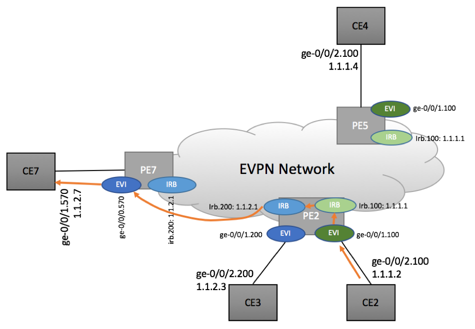
Our setup will be comprised of three PE and four CE devices as shown below:
Two Layer 3 subnets are used in this topology – 1.1.1.0/24 depicted as Green IRB and 1.1.2.0/24 depicted as Blue IRB. Both IRBs belong the same L3 VRF. Green and Blue IRBs are configured as L3 gateways for corresponding EVI interfaces.
PE2 device has local configuration for both Blue and Green EVI and IRB instances. PE5 has only Blue EVI/IRB and PE7 has Green EVI/IRB.
Logical Configuration
IP and MAC Assignments
| Device | IP | MAC |
| CE2 | 1.1.1.2 | 00:0c:29:8a:79:e8 |
| CE3 | 1.1.2.3 | 00:0c:29:de:e3:64 |
| CE4 | 1.1.1.4 | 00:0c:29:82:c2:a9 |
| CE7 | 1.1.2.7 | 00:0c:29:31:01:ed |
| PE2 IRB100 | 1.1.1.1 | 00:00:5e:01:00:00 |
| PE2 IRB200 | 1.1.2.1 | 00:00:5e:02:00:00 |
| PE5 IRB100 | 1.1.1.1 | 00:00:5e:01:00:00 |
| PE7 IRB200 | 1.1.2.1 | 00:00:5e:02:00:00 |
PE2
Complete configuration on GitHub: PE2
CUSTOMER-A {
    instance-type virtual-switch;
    interface ge-0/0/1.0;
    interface ge-0/0/2.0;
    route-distinguisher 120.0.2.2:100;
    vrf-target target:100:100;
    protocols {
        evpn {
            extended-vlan-list [ 100 200 ];
            default-gateway do-not-advertise;
        }
    }
    bridge-domains {
        BD100 {
            vlan-id 100;
            routing-interface irb.100;
        }
        BD200 {
            vlan-id 200;
            routing-interface irb.200;
        }
    }
}

CUSTOMER-A-L3 {
    instance-type vrf;
    interface irb.100;
    interface irb.200;
    route-distinguisher 120.0.2.2:101;
    vrf-target target:100:101;
    vrf-table-label;
    protocols {
        evpn {
            ip-prefix-routes {
                advertise direct-nexthop;
            }
        }
    }
}
PE5
Complete configuration on GitHub: PE5
root@PE5> show configuration routing-instances
CUSTOMER-A {
    instance-type virtual-switch;
    interface ge-0/0/1.0;
    route-distinguisher 120.0.2.1:100;
    vrf-target target:100:100;
    protocols {
        evpn {
            extended-vlan-list 100;
            default-gateway do-not-advertise;
        }
    }
    bridge-domains {
        BD100 {
            vlan-id 100;
            routing-interface irb.100;
        }
    }
}

CUSTOMER-A-L3 {
    instance-type vrf;
    interface irb.100;
    route-distinguisher 120.0.2.1:101;
    vrf-target target:100:101;
    vrf-table-label;
    protocols {
        evpn {
            ip-prefix-routes {
                advertise direct-nexthop;
            }
        }
    }
}
PE7
Complete configuration on GitHub: PE7
root@PE7> show configuration routing-instances
CUSTOMER-A {
    instance-type virtual-switch;
    interface ge-0/0/0.0;
    route-distinguisher 120.0.2.7:100;
    vrf-target target:100:100;
    protocols {
        evpn {
            extended-vlan-list 200;
        }
    }
    bridge-domains {
        BD100 {
            vlan-id 200;
            routing-interface irb.200;
        }
    }
}
CUSTOMER-A-L3 {
    instance-type vrf;
    interface irb.200;
    route-distinguisher 120.0.2.7:101;
    vrf-target target:100:101;
    vrf-table-label;
    protocols {
        evpn {
            ip-prefix-routes {
                advertise direct-nexthop;
            }
        }
    }
}
Traffic flow scenarios
In this lab, we will review traffic flows originated and terminated on CE7. We have packet sniffer connected to PE7’s MPLS Network-facing interfaces, allowing us to capture packets with MPLS headers as they enter/leave PE device.
Scenario 1: CE7 <-> CE 3 traffic flow
In this scenario, we are reviewing traffic exchange between CE7 and CE3 devices. This is the simplest use case, as both CE3 and CE7 belong to the same L3 network. As such, no L3 routing is need and traffic is carried as Ethernet frames. This is not an inter-VLAN routing use case, but it’s included for completeness.
Scenario 1a: CE7 -> CE3
CE7:
CE7: $ traceroute 1.1.2.3
traceroute to 1.1.2.3 (1.1.2.3), 30 hops max, 60 byte packets
 1   1.1.2.3 (1.1.2.3)  59.903 ms  60.074 ms 59.603 ms

CE7:$ arp -a | grep 1.1.2.3
1.1.2.3 at 00:0c:29:de:e3:64 [ether] on ens192
PE7:
root@PE7> show evpn database  extensive
VLAN ID: 200, MAC address:: 00:0c:29:de:e3:64
Nexthop ID: 1048580
  Source: 120.0.2.2, Rank: 1, Status: Active                ß PE2
    MAC label: 300192
    Timestamp: Apr 29 07:12:07 (0x59047507)
    State: <Remote-To-Local-Adv-Done>
    IP address: 1.1.2.3
      L3 route: 1.1.2.3/32, L3 context: CUSTOMER-A-L3 (irb.200)
PE2:
root@PE2> show route label 300192

mpls.0: 21 destinations, 22 routes (21 active, 0 holddown, 0 hidden)
...
300192

*[EVPN/7] 00:04:31, routing-instance CUSTOMER-A,
route-type Ingress-MAC, vlan-id 100
                      to table CUSTOMER-A.evpn-mac.0

[EVPN/7] 00:01:52, routing-instance CUSTOMER-A,
route-type Ingress-MAC, vlan-id 200
                      to table CUSTOMER-A.evpn-mac.0
Packet Capture:
MultiProtocol Label Switching Header, Label: 800202 (PE2), Exp: 0, S: 0, TTL: 255

MultiProtocol Label Switching Header, Label: 300192, Exp: 0, S: 1, TTL: 255

Ethernet II, Src: CE7(00:0c:29:31:01:ed), Dst: CE3(00:0c:29:de:e3:64)
802.1Q Virtual LAN, PRI: 0, CFI: 0, ID: 200
Internet Protocol Version 4, Src: 1.1.2.7, Dst: 1.1.2.3
Internet Control Message Protocol
Complete packet capture on GitHub: PCAP, Text, Text collapsed.
Scenario 1b: CE3 -> CE7
This scenario is a mirror image of the previous CE7 -> CE3 scenario. Detailed output is omitted for brevity.
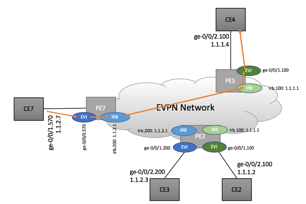
Scenario 2: CE7 <-> CE 2 traffic flow
CE7 <-> CE2 traffic flow scenario represents an asymmetric configuration, where PE7 has no direct visibility into destination ‘Green’ Domain, while PE2 has the knowledge of PE7’s ‘Blue’ network.
As such, we might expect to see some asymmetry in traffic flow from and to CE7.
Scenario 2a: CE7 to CE2
Packet capture performed on PE7 demonstrates that CE7 to CE2 packet stream gets forwarded via PE5 device as shown below:
Clearly, this is sub-optimal scenario as packets are going via PE5 device, instead of more optimal PE7->PE2 path. Let’s review the routing information to understand the root cause.
CE7 resides on 1.1.2.0/24 subnet and has no direct 1.1.1.0/24 reachability. In order to send traffic to CE2, CE7 has to to rely on its default gateway 1.1.2.1. This gateway IP is configured on PE7’s ‘Blue’ IRB interface.
When PE7 gets an IP packet destined to 1.1.1.2, it performs an IP routing lookup to determine where to send this frame:
root@PE7> show route 1.1.1.2
CUSTOMER-A-L3.inet.0: 5 destinations, 7 routes
1.1.1.0/24
> to 120.0.3.32 via ge-0/0/1.570, Push 17, Push 800205(top)
> to 120.0.3.32 via ge-0/0/1.570, Push 17, Push 800202(top)
As you can see, specific 1.1.1.1/32 prefix is not being advertised by any of the devices. Instead, an aggregate 1.1.1.0/24 is being originated by both PE2 and PE5, as both devices have ‘Green’ IRB interfaces. PE7 has no way of determining which of two PEs has more optimal path to the specific 1.1.1.2/32 IP it is trying to reach and depending on the load-balancing policy, can pick either of them. In our case, PE5 device was selected leading to sub-optimal traffic flow.
When PE5 gets the packet, it performs a lookup in L3 VRF and determines that the packet should be redirected to PE2:
root@PE5> show route label 17
mpls.0: 21 destinations, 21 routes (21 active, 0 holddown, 0 hidden)
17                 *[VPN/0] 22:49:56
> via lsi.1 (CUSTOMER-A-L3), Pop


root@PE5> show route 1.1.1.2 table CUSTOMER-A-L3.inet.0
CUSTOMER-A-L3.inet.0: 5 destinations, 7 routes
1.1.1.2/32         *[EVPN/7] 13:33:21
> to 120.0.3.26 via ge-0/0/0.540, Push 300192, Push 800202(top)
It’s interesting to note that the information about 1.1.1.2/32 was derived from Type 2 advertisement received by PE5 from PE2:
root@PE5>  show route receive-protocol bgp 120.0.2.2
  2:120.0.2.2:100::100::00:0c:29:8a:79:e8::1.1.1.2/304 MAC/IP
*                         120.0.2.2                    100        I
Scenario 2b: CE2 to CE7
Traffic in the reverse direction takes a different path. PE2 locally routes packet received via VLAN 100 to IRB100 (Green) and IRB200 (Blue).
When CE2 (1.1.1.2) needs to send packets to CE7 (1.1.2.7), it uses default gateway (1.1.1.1) that is configured on PE2. PE2, after receiving packets from CE2 does L3 lookup and forwards packets from IRB.100 to IRB.200. After that, PE2 can deliver packets to PE7’s EVI.
PE2:
root@PE2> show route 1.1.2.7 table CUSTOMER-A-L3.inet.0
CUSTOMER-A-L3.inet.0: 8 destinations, 10 routes
1.1.2.7/32         *[EVPN/7] 15:48:24
> to 120.0.3.10 via ge-0/0/0.503, Push 299952, Push 800207(top)
PE7 pops MPLS label and delivers packets to CE7:
root@PE7> show route label 299952
mpls.0: 21 destinations, 21 routes (21 active, 0 holddown, 0 hidden)

299952             *[EVPN/7] 15:53:02, routing-instance CUSTOMER-A, route-type Ingress-MAC, vlan-id 200
to table CUSTOMER-A.evpn-mac.0


root@PE7> show evpn database
Instance: CUSTOMER-A
VLAN  DomainId  MAC address        Active source                  Timestamp        IP address
100             00:0c:29:82:c2:a9  120.0.2.5                    1.1.1.4
100             00:0c:29:8a:79:e8  120.0.2.2                    1.1.1.2
200             00:00:5e:02:00:00  irb.200                      1.1.2.1
200             00:0c:29:31:01:ed  ge-0/0/0.0                   1.1.2.7
200             00:0c:29:de:e3:64  120.0.2.2                    1.1.2.3
Packet capture:
MultiProtocol Label Switching Header, Label: 299952, Exp: 0, S: 1, TTL: 253
Ethernet II, Src: irb200(00:00:5e:02:00:00), Dst: CE7 (00:0c:29:31:01:ed)
802.1Q Virtual LAN, PRI: 0, CFI: 0, ID: 200
Internet Protocol Version 4, Src: 1.1.1.2, Dst: 1.1.2.7
Internet Control Message Protocol
Complete packet capture on GitHub: PCAP, Text, Text collapsed.
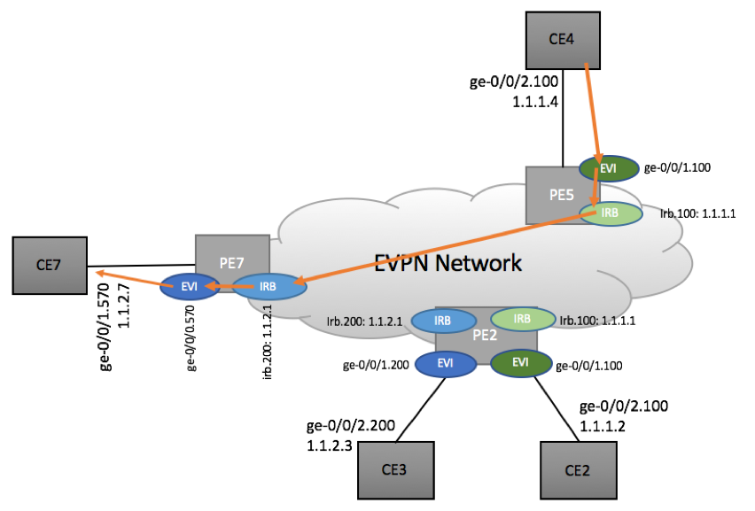
Scenario 3: CE7 <-> CE 4 traffic flow
CE7 <-> CE4 traffic flow scenario represents symmetric scenario where PE devices have no visibility into each other’s EVI domains and must rely on IP routing in both directions.
Scenario 3a: CE7 to CE4
Similar to previously described CE7 to CE2 scenario, PE7 does IP lookup to determine 1.1.1.4’s reachability.
PE7:
root@PE7> show route 1.1.1.4

CUSTOMER-A-L3.inet.0: 5 destinations, 7 routes

1.1.1.0/24

*[EVPN/170] 1d 06:01:16
> to 120.0.3.32 via ge-0/0/1.570, Push 17, Push 800205(top)

[EVPN/170] 1d 06:01:16
> to 120.0.3.32 via ge-0/0/1.570, Push 17, Push 800202(top)
In our scenario, PE5 was selected as the egress LER, although PE2 could also have been selected.
When PE5 receives the packets, it forwards packets to CE4.
root@PE5> show route label 17 extensive

mpls.0: 21 destinations, 21 routes
        *VPN    Preference: 0
                Next hop type: Router, Next hop index: 0
                Address: 0xb39e950
                Next-hop reference count: 1
                Next hop: via lsi.1 (CUSTOMER-A-L3), selected
                Label operation: Pop
                Load balance label: None;
                Label element ptr: 0xb39fc00
                Label parent element ptr: 0x0
                Label element references: 1
                Label element child references: 0
                Label element lsp id: 0
                Session Id: 0x0
                State: <Active NotInstall Int Ext LsiL3>
                Age: 1d 8:47:59
                Validation State: unverified
                Task: RT
                AS path: I

root@PE5> show route 1.1.1.4/32 table CUSTOMER-A-L3.inet.0 extensive

CUSTOMER-A-L3.inet.0: 5 destinations, 7 routes
1.1.1.4/32 (1 entry, 1 announced)
        *EVPN   Preference: 7
                Next hop type: Interface, Next hop index: 0
                Address: 0xb39f850
                Next-hop reference count: 2
                Next hop: via irb.100, selected
                State: <Active Int Ext>
                Age: 49
                Validation State: unverified
                Task: CUSTOMER-A-evpn
                Announcement bits (1): 0-Resolve tree 4
                AS path: I

root@PE5> show arp | match 1.1.1.4
00:0c:29:82:c2:a9 1.1.1.4         1.1.1.4                   irb.100 [ge-0/0/1.0]

Please note that PE5 ge-0/0/1’s interface is configured as trunk:

root@PE5> show configuration interfaces ge-0/0/1
unit 0 {
    family bridge {
        interface-mode trunk;
        vlan-id-list 100;
    }
}
Packet capture:
…
MultiProtocol Label Switching Header, Label: 800205, Exp: 0, S: 0, TTL: 255
MultiProtocol Label Switching Header, Label: 17, Exp: 0, S: 1, TTL: 255
Internet Protocol Version 4, Src: 1.1.2.7, Dst: 1.1.1.4
Internet Control Message Protocol
Complete packet capture on GitHub: PCAP, Text, Text collapsed.
Scenario 3b: CE4 to CE7
PE5:
root@PE5> show route 1.1.2.7


CUSTOMER-A-L3.inet.0: 5 destinations, 7 routes
+ = Active Route, - = Last Active, * = Both


1.1.2.0/24         *[EVPN/170] 07:51:04
                    > to 120.0.3.26 via ge-0/0/0.540, Push 16, Push 800207(top)
                    [EVPN/170] 1d 06:20:45
                    > to 120.0.3.26 via ge-0/0/0.540, Push 17, Push 800202(top)
PE7:
root@PE7> show route label 16 extensive

mpls.0: 21 destinations, 21 routes
16  (1 entry, 0 announced)
        *VPN    Preference: 0
                Next hop type: Router, Next hop index: 0
                Address: 0xb39ea70
                Next-hop reference count: 1
                Next hop: via lsi.256 (CUSTOMER-A-L3), selected
                Label operation: Pop
                Load balance label: None;
                Label element ptr: 0xb39e9a0
                Label parent element ptr: 0x0
                Label element references: 1
                Label element child references: 0
                Label element lsp id: 0
                Session Id: 0x0
                State: <Active NotInstall Int Ext LsiL3>
                Age: 1d 6:44:41
                Validation State: unverified
                Task: RT
                AS path: I


CUSTOMER-A-L3.inet.0: 5 destinations, 7 routes (5 active, 0 holddown, 0 hidden)

1.1.2.7/32 (1 entry, 1 announced)
        *EVPN   Preference: 7
                Next hop type: Interface, Next hop index: 0
                Address: 0xb39cd30
                Next-hop reference count: 2
                Next hop: via irb.200, selected
                State: <Active Int Ext>
                Age: 7:01
                Validation State: unverified
                Task: CUSTOMER-A-evpn
                Announcement bits (1): 0-Resolve tree 4
                AS path: I

root@PE7> show arp
00:0c:29:31:01:ed 1.1.2.7         1.1.2.7                   irb.200 [ge-0/0/0.0]

Please note that ge-0/0/0 is configured as a trunk:

root@PE7> show configuration interfaces ge-0/0/0
unit 0 {
    family bridge {
        interface-mode access;
        vlan-id 200;
    }
}
Wireshark capture:
…
MultiProtocol Label Switching Header, Label: 16, Exp: 0, S: 1, TTL: 254
Internet Protocol Version 4, Src: 1.1.1.4, Dst: 1.1.2.7
Internet Control Message Protocol
Complete packet capture on GitHub: PCAP, Text, Text collapsed.
Complete Lab Repository with configuration files and packet captures.