Cisco and Juniper Segment Routing Interoperability design with configuration examples. IS-IS based IGP topology.
Complete configuration repository on GitHub: https://github.com/bgphelp/blueprints/tree/master/1-SR-Cisco-Juniper
Physical Topology
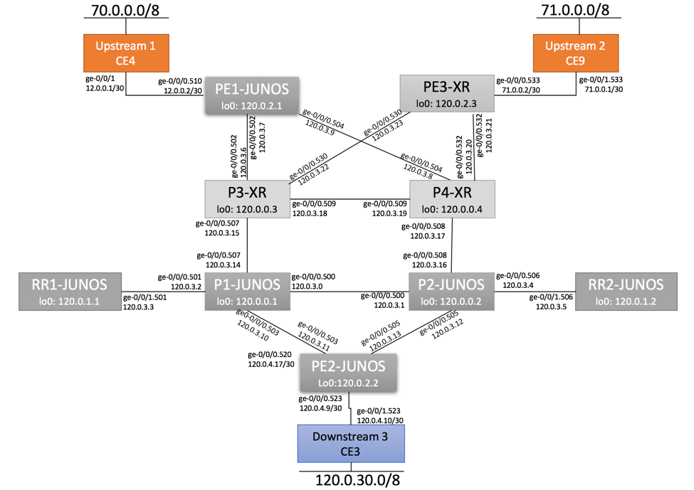
Lab Physical Topology is depicted below. In order to demonstrate Segment Routing Interoperability, both Cisco IOS-XR Nodes (XR version 6.1.1) and Juniper Nodes (JunOS version 17.1) were used in this topology.

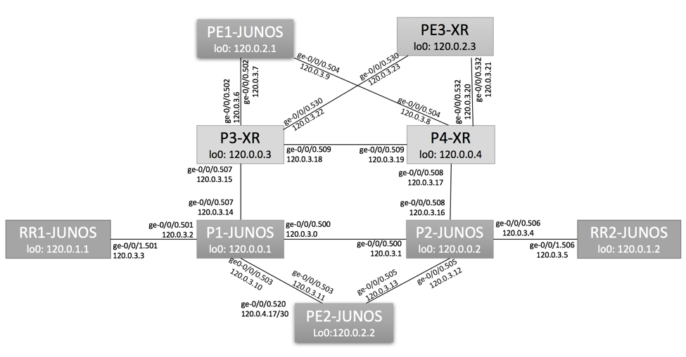
IGP-Enabled Links
IS-IS protocol is used to carry infrastructure Loopback and Point-to-Point routes.
Single Level 2 area was used in this lab.

SR-Enabled Nodes
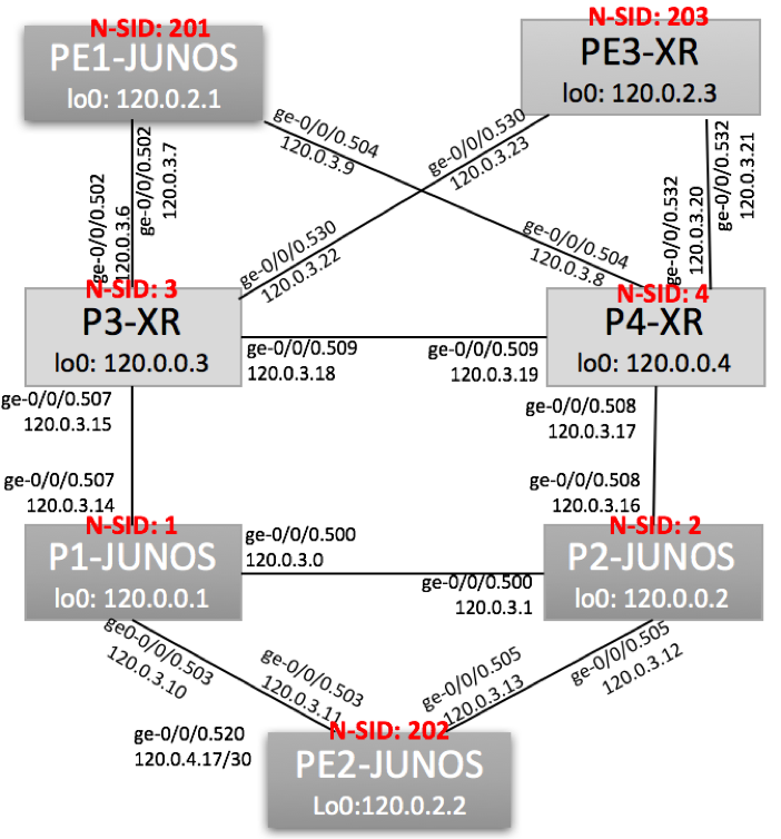
SR was configured on all P and PE Nodes. SR was not enabled on Route-Reflectors.
Node Segment Identifiers (Node-SID) values were manually assigned as shown below:

BGP Adjacencies
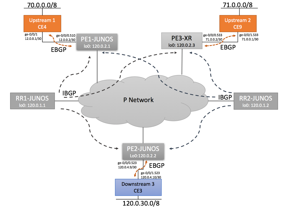
EBGP Sessions were configured with Upstream and Downstream Nodes.
Two Route-Reflectors are configured for IPv4 Unicast Address Family.

IS-IS and Segment Routing Configuration
Cisco IOS-XR Nodes
Key Configuration Elements:
- Specify SR Global Node-SID to match Juniper’s Global Block settings.
- Enable Segment Routing MPLS
- Specify Unique Node SID by configuring Prefix-SID Index for Address Family IPv4 Unicast
P-3
https://github.com/bgphelp/blueprints/blob/master/1-SR-Cisco-Juniper/P3.cfg
router isis main
 is-type level-2-only
 net 49.0002.0120.0000.0003.00
 segment-routing global-block 800000 804095
 log adjacency changes
 address-family ipv4 unicast
  metric-style wide
  segment-routing mpls
 !
 interface Loopback0
  passive
  address-family ipv4 unicast
   prefix-sid index 3        <--- Configure unique Node-SID
  !
 !

interface GigabitEthernet0/0/0/0.502
  point-to-point
  address-family ipv4 unicast
  !
 !
 interface GigabitEthernet0/0/0/0.507
  point-to-point
  address-family ipv4 unicast
  !
 !

interface GigabitEthernet0/0/0/0.509
 point-to-point
 address-family ipv4 unicast
!
!

interface GigabitEthernet0/0/0/0.530
 point-to-point
  address-family ipv4 unicast
 !
 !
!
end
P4
https://github.com/bgphelp/blueprints/blob/master/1-SR-Cisco-Juniper/P4.cfg
Juniper Nodes
P-1
protocols {
 isis {
        source-packet-routing {
            node-segment ipv4-index 1;  <-- Configure unique Node-SID
        }
        level 2 wide-metrics-only;
        level 1 disable;
        interface all {
            point-to-point;
        }
        interface fxp0.0 {
            disable;
        }
    }
}
P2
Monitoring End-To-End Reachability
Cisco Ingress PE to Juniper Egress PE via mixed Cisco/Juniper MPLS Core
Ingress Cisco PE (PE-3)
From PE-3, we will validate end-to-end reachability to prefix 120.0.30.0/24 behind Downstream CE-3. CE-3 is directly connected to PE-2, customer prefix is advertised via EBGP.
PE-2’s Loopback address is 120.0.2.2 and Node-SID 202. We expect to use Labeled-Switched Path over BGP-free Core. MPLS Label Value will be calculated as
MPLS Label = Global Block + Node SID
MPLS Label for PE-1: 800,000 + 201 = 800,201
MPLS Label for PE-2: 800,000 + 202 = 800,202
MPLS Label for PE-3: 800,000 + 203 = 800,203
RP/0/0/CPU0:PE3-XR#show route 120.0.30.0/24  detail

Routing entry for 120.0.30.0/24
  Known via "bgp 100", distance 200, metric 0
  Tag 65001, type internal
  Routing Descriptor Blocks
    120.0.2.2, from 120.0.1.1
      Route metric is 0
      Label: None
      Tunnel ID: None
      Binding Label: None
      Extended communities count: 0
      NHID:0x0(Ref:0)

  Route version is 0x3 (3)
  No local label
  IP Precedence: Not Set
  QoS Group ID: Not Set
  Flow-tag: Not Set
  Fwd-class: Not Set
  Route Priority: RIB_PRIORITY_RECURSIVE (12) SVD Type RIB_SVD_TYPE_LOCAL
  Download Priority 4, Download Version 3565
  No advertising protos.


RP/0/0/CPU0:PE3-XR# show cef 120.0.30.0/24 detail
...

   via 120.0.2.2/32, 2 dependencies, recursive [flags 0x6000]
    path-idx 0 NHID 0x0 [0xa1407ff4 0x0]
    next hop 120.0.2.2/32 via 120.0.2.2/32

    Load distribution: 0 1 (refcount 1)

    Hash  OK  Interface                 Address
    0     Y   GigabitEthernet0/0/0/0.530 120.0.3.22
    1     Y   GigabitEthernet0/0/0/0.532 120.0.3.20
Validate Next-Hop Reachability:
RP/0/0/CPU0:PE3-XR#show route  120.0.2.2/32 detail

Routing entry for 120.0.2.2/32
  Known via "isis main", distance 115, metric 30, labeled SR, type level-2

  Routing Descriptor Blocks
    120.0.3.22, from 120.0.2.2, via GigabitEthernet0/0/0/0.530
      Route metric is 30
      Label: 0xc35ca (800202)
      Tunnel ID: None
      Binding Label: None
      Extended communities count: 0
      Path id:2       Path ref count:0
      NHID:0x4(Ref:13)
    120.0.3.20, from 120.0.2.2, via GigabitEthernet0/0/0/0.532
      Route metric is 30
      Label: 0xc35ca (800202)
      Tunnel ID: None
      Binding Label: None
      Extended communities count: 0
      Path id:1       Path ref count:0
      NHID:0x3(Ref:12)

  Route version is 0xf (15)
  Local Label: 0xc35ca (800202)
  IP Precedence: Not Set
  QoS Group ID: Not Set
  Flow-tag: Not Set
  Fwd-class: Not Set
  Route Priority: RIB_PRIORITY_NON_RECURSIVE_MEDIUM (7) SVD Type RIB_SVD_TYPE_LOCAL
  Download Priority 1, Download Version 3590
  No advertising protos.

RP/0/0/CPU0:PE3-XR#show cef  120.0.2.2/32

120.0.2.2/32, version 3590, internal 0x1000001 0x81 (ptr 0xa1407ff4) [2], 0x0 (0xa13d37e8), 0xa28 (0xa16e80d4)
 local adjacency 120.0.3.22
 Prefix Len 32, traffic index 0, precedence n/a, priority 1
   via 120.0.3.22/32, GigabitEthernet0/0/0/0.530, 11 dependencies, weight 0, class 0 [flags 0x0]
    path-idx 0 NHID 0x0 [0xa10b9100 0x0]
    next hop 120.0.3.22/32
    local adjacency
     local label 800202      labels imposed {800202}
   via 120.0.3.20/32, GigabitEthernet0/0/0/0.532, 11 dependencies, weight 0, class 0 [flags 0x0]
    path-idx 1 NHID 0x0 [0xa10b92f8 0x0]
    next hop 120.0.3.20/32
    local adjacency
     local label 800202      labels imposed {800202}

RP/0/0/CPU0:PE3-XR#show isis route 120.0.2.2/32 detail
L2 120.0.2.2/32 [30/115] medium priority
     via 120.0.3.20, GigabitEthernet0/0/0/0.532, P4-XR, SRGB Base: 800000, Weight: 0
     via 120.0.3.22, GigabitEthernet0/0/0/0.530, P3-vXR, SRGB Base: 800000, Weight: 0
     src PE2-vMX.00-00, 120.0.2.2, prefix-SID index 202, R:0 N:1 P:0 E:0 V:0 L:0
Transit Cisco P Nodes
Label Swap 800,202 -> 800,2002 as we are using Global Node SID for PE-2 reachability.
RP/0/0/CPU0:P3-vXR#show mpls forwarding
…
800202 800202      SR Pfx (idx 202)   Gi0/0/0/0.507 120.0.3.14      6922


RP/0/0/CPU0:P4-XR#show mpls forwarding
…
800202 800202      SR Pfx (idx 202)   Gi0/0/0/0.508 120.0.3.16      749232
Transit Juniper P Nodes
Juniper P routers P-1 and P-2 are penultimate hops for PE-2, as such MPLS Label Action should be ‘Pop’:
show route table mpls.0
…
800202             *[L-ISIS/14] 2d 02:28:53, metric 10
                    > to 120.0.3.11 via ge-0/0/0.503, Pop
800202(S=0)        *[L-ISIS/14] 00:02:41, metric 10
                    > to 120.0.3.11 via ge-0/0/0.503, Pop

root@P2-vMX> show route table mpls.0
…
800202             *[L-ISIS/14] 2d 02:28:19, metric 10
                    > to 120.0.3.13 via ge-0/0/0.505, Pop
800202(S=0)        *[L-ISIS/14] 00:05:59, metric 10
                    > to 120.0.3.13 via ge-0/0/0.505, Pop
Juniper Egress PE router
Juniper Egress PE will receive untagged traffic due to MPLS Pop action performed by penultimate nodes and will do regular L3 IP Lookup.
Juniper Ingress PE to Cisco Egress PE via mixed Cisco/Juniper MPLS Core
Ingress PE (PE-2)
From Juniper PE-2, we will validate end-to-end reachability to prefix 71.0.0.0/8 behind Upstream CE-9. CE-9 is directly connected to Cisco PE-3, prefix is advertised via EBGP.
P3-2’s Loopback address is 120.0.2.3 and Node-SID 203. We expect to use Labeled-Switched Path over BGP-free Core. MPLS Label Value will be calculated as
MPLS Label = Global Block + Node SID
MPLS Label for PE-1: 800,000 + 201 = 800,201
MPLS Label for PE-2: 800,000 + 202 = 800,202
MPLS Label for PE-3: 800,000 + 203 = 800,203
root@PE2-vMX> show route 71.0.0.0/8

inet.0: 74 destinations, 81 routes (65 active, 0 holddown, 9 hidden)
+ = Active Route, - = Last Active, * = Both

71.0.0.0/8         *[BGP/170] 03:44:09, localpref 100, from 120.0.1.1
                      AS path: 702 I, validation-state: unverified
                    > to 120.0.3.12 via ge-0/0/0.505, Push 800203
                      to 120.0.3.10 via ge-0/0/0.503, Push 800203

                    [BGP/170] 03:44:09, localpref 100, from 120.0.1.2
                      AS path: 702 I, validation-state: unverified
                    > to 120.0.3.12 via ge-0/0/0.505, Push 800203
                      to 120.0.3.10 via ge-0/0/0.503, Push 800203


root@PE2-vMX> show route 71.0.0.0/8 extensive

inet.0: 74 destinations, 81 routes (65 active, 0 holddown, 9 hidden)
71.0.0.0/8 (2 entries, 1 announced)
TSI:
KRT in-kernel 71.0.0.0/8 -> {indirect(1048575)}
        *BGP    Preference: 170/-101
                Next hop type: Indirect, Next hop index: 0
                Address: 0xb39e1d0
                Next-hop reference count: 3
                Source: 120.0.1.1
                Next hop type: Router, Next hop index: 0
                Next hop: 120.0.3.12 via ge-0/0/0.505, selected
                Label operation: Push 800203
                Label TTL action: prop-ttl
                Load balance label: Label 800203: None;
                Label element ptr: 0xb39f780
                Label parent element ptr: 0x0
                Label element references: 4
                Label element child references: 0
                Label element lsp id: 0
                Session Id: 0x0
                Next hop: 120.0.3.10 via ge-0/0/0.503
                Label operation: Push 800203
                Label TTL action: prop-ttl
                Load balance label: Label 800203: None;
                Label element ptr: 0xb39f780
                Label parent element ptr: 0x0
                Label element references: 4
                Label element child references: 0
                Label element lsp id: 0
                Session Id: 0x0
                Protocol next hop: 120.0.2.3
                Indirect next hop: 0xb2b3300 1048575 INH Session ID: 0x151
                State: <Active Int Ext>
                Local AS:   100 Peer AS:   100
                Age: 3:46:16            Metric2: 30
                Validation State: unverified
                ORR Generation-ID: 0
                Task: BGP_100.120.0.1.1
                Announcement bits (2): 0-KRT 4-Resolve tree 4
                AS path: 702 I (Originator)
                Cluster list:  0.0.0.1
                Originator ID: 120.0.2.3
                Accepted
                Localpref: 100
                Router ID: 1.1.1.50
                Indirect next hops: 1
                        Protocol next hop: 120.0.2.3 Metric: 30
                        Indirect next hop: 0xb2b3300 1048575 INH Session ID: 0x151
                        Indirect path forwarding next hops: 2
                                Next hop type: Router
                                Next hop: 120.0.3.12 via ge-0/0/0.505
                                Session Id: 0x0
                                Next hop: 120.0.3.10 via ge-0/0/0.503
                                Session Id: 0x0
                                    120.0.2.3/32 Originating RIB: inet.3
                                      Metric: 30                               Node path count: 1
                                      Forwarding nexthops: 2
                                                Nexthop: 120.0.3.12 via ge-0/0/0.505

…
Transit Juniper P Nodes
root@P1-vMX> show route table mpls.0
…
800203             *[L-ISIS/14] 15:09:31, metric 20
> to 120.0.3.15 via ge-0/0/0.507, Swap 800203

root@P2-vMX> show route table mpls.0
800203             *[L-ISIS/14] 02:46:27, metric 20
> to 120.0.3.17 via ge-0/0/0.508, Swap 800203
Transit Cisco P Nodes
RP/0/0/CPU0:P3-vXR#show mpls forwarding
...
800203 Pop         SR Pfx (idx 203)   Gi0/0/0/0.530 120.0.3.23      908401

RP/0/0/CPU0:P4-XR#show mpls forwarding
...
800203 Pop         SR Pfx (idx 203)   Gi0/0/0/0.532 120.0.3.21      889374
Cisco Egress PE router
Cisco Egress PE will receive untagged traffic due to MPLS Pop action performed by penultimate nodes and will do regular L3 IP Lookup.
Configuration
Complete configuration repository on GitHub: https://github.com/bgphelp/blueprints/tree/master/1-SR-Cisco-Juniper
