SR troubleshooting in IS-IS environment
Useful Commands:
- show mpls interface
- show isis adjacency
- show isis database extensive
- show route table inet.3
Network Configuration
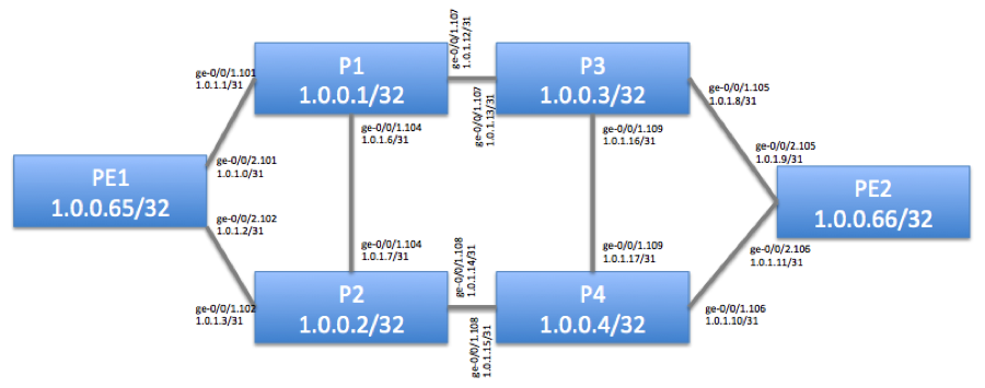
Figure 1 depicts our physical topology. Our goal is to verify that PE1 to PE2 LSP is up & running.

Basic SR configuration was applied to the devices:
PE1
root@vsrx1-pe1> show configuration interfaces
unit 0 {
family inet {
address 1.0.0.65/32;
}
family iso {
address 49.0002.0120.0002.0065.00;
}
family mpls;
}
ge-0/0/2 {
vlan-tagging;
unit 101 {
vlan-id 101;
family inet {
address 1.0.1.0/31;
}
family iso;
family mpls;
}
unit 102 {
vlan-id 102;
family inet {
address 1.0.1.2/31;
}
family iso;
family mpls;
}
}
root@vsrx1-pe1> show configuration protocols
mpls {
interface all;
label-history;
}
isis {
source-packet-routing {
node-segment ipv4-index 65;
}
level 1 disable;
level 2 wide-metrics-only;
}
PE2
root@vsrx2-pe2# show interfaces
lo0 {
unit 0 {
family inet {
address 1.0.0.66/32;
}
family iso {
address 49.0002.0120.0002.0066.00;
}
family mpls;
}
}
ge-0/0/2 {
vlan-tagging;
unit 105 {
vlan-id 105;
family inet {
address 1.0.1.9/31;
}
family iso;
family mpls;
}
unit 106 {
vlan-id 106;
family inet {
address 1.0.1.11/31;
}
family iso;
family mpls;
}
}
root@vsrx2-pe2# show protocols
mpls {
interface ge-0/0/1.0 {
disable;
}
interface fxp0.0 {
disable;
}
interface all;
}
isis {
source-packet-routing {
node-segment ipv4-index 66;
}
level 1 disable;
level 2 wide-metrics-only;
interface all {
point-to-point;
}
}
P1
root@vsrx3-p1> show configuration interfaces
ge-0/0/1 {
vlan-tagging;
unit 101 {
vlan-id 101;
family inet {
address 1.0.1.1/31;
}
family iso;
family mpls;
}
unit 103 {
vlan-id 103;
family inet {
address 1.0.1.4/31;
}
family iso;
family mpls;
}
unit 104 {
vlan-id 104;
family inet {
address 1.0.1.6/31;
}
family iso;
family mpls;
}
unit 107 {
vlan-id 107;
family inet {
address 1.0.1.12/31;
}
family iso;
family mpls;
}
}
lo0 {
unit 0 {
family inet {
address 1.0.0.1/32;
}
family iso {
address 49.0002.0120.0002.0001.00;
}
family mpls;
}
}
root@vsrx3-p1> show configuration protocols
mpls {
interface all;
}
isis {
source-packet-routing {
node-segment ipv4-index 1;
}
level 1 disable;
level 2 wide-metrics-only;
interface all {
point-to-point;
}
}
P2, P3, P4 configuration
The rest of P-devices are configured in a similar way. IPv4 Index ID needs to be unique for every device.
Troubleshooting Commands
Our goal is to ensure that end-to-end MPSL LSP is established between PE1 and PE2 devices
MPLS is enabled on the interfaces
root@vsrx1-pe1> show mpls interface
Interface State Administrative groups (x: extended)
ge-0/0/2.101 Up <none>
ge-0/0/2.102 Up <none>
IS-IS adjacency is established
root@vsrx1-pe1> show isis adjacency
Interface System L State Hold (secs) SNPA
ge-0/0/2.101 vsrx3-p1 2 Up 21
ge-0/0/2.102 vsrx4-p2 2 Up 25
IS-IS database contains SR attributes
root@vsrx1-pe1> show isis database vsrx2-pe2.00-00 extensive
IS-IS level 1 link-state database:
IS-IS level 2 link-state database:
vsrx2-pe2.00-00 Sequence: 0x5b, Checksum: 0xc546, Lifetime: 643 secs
IPV4 Index: 66
Node Segment Blocks Advertised:
Start Index : 0, Size : 4096, Label-Range: [ 800000, 804095 ]
IS neighbor: vsrx5-p3.00 Metric: 10
Two-way fragment: vsrx5-p3.00-00, Two-way first fragment: vsrx5-p3.00-00
P2P IPv4 Adj-SID: 299808, Weight: 0, Flags: –VL–
IS neighbor: vsrx6-p4.00 Metric: 10
Two-way fragment: vsrx6-p4.00-00, Two-way first fragment: vsrx6-p4.00-00
P2P IPv4 Adj-SID: 299824, Weight: 0, Flags: –VL–
IP prefix: 1.0.0.66/32 Metric: 0 Internal Up
IP prefix: 1.0.1.8/31 Metric: 10 Internal Up
IP prefix: 1.0.1.10/31 Metric: 10 Internal Up
There is a path in inet.3 table
root@vsrx1-pe1> show route 1.0.0.66 table inet.3
inet.3: 5 destinations, 5 routes (5 active, 0 holddown, 0 hidden)
+ = Active Route, – = Last Active, * = Both
1.0.0.66/32 *[L-ISIS/14] 00:53:23, metric 30
> to 1.0.1.1 via ge-0/0/2.101, Push 800066
to 1.0.1.3 via ge-0/0/2.102, Push 800066
