Step-by-step migration from LDP-based design to Segment Routing topology in Juniper environment. In this example, we will be using IS-IS as IGP protocol.
Continue reading “LDP to Segment Routing (also known as SR and SPRING) Migration Steps”
Tag: BGP-Free
Migrating to BGP-Free Core in Juniper Environment
Discussion on how to migrate to BGP-Free Core by deploying MPLS as network tunneling mechanism. Document provides step-by-step migration steps for a Juniper-based network.
Continue reading “Migrating to BGP-Free Core in Juniper Environment”
BGP Free Core
What is a BGP-Free Core?
As the name suggests, BGP-Free Core is a network deployment approach where Service Providers’ Core routers do not run BGP. This is done by employing a tunneling mechanism of some sort, most commonly MPLS.
What are the advantages of a BGP-Free Core?
There are many, to list just a few:
- Core devices do not need to be capable of supporting a large number of IPv4/IPv6 routes, allowing you to deploy devices with limited RIB and FIB Capacity
- As there is no BGP, Core devices will not be impacted by BGP-related issues, such as high CPU utilization during massive BGP re-convergence
- By not running BGP, you eliminate one of the attack vectors – if a new BGP security vulnerability were to be discovered, Core devices would not be impacted
- Operators’ mistakes associated with BGP configuration can be eradicated
- New services such as MPLS VPN, IPv6, EVPN can be introduced without modifying the Core routers
- If deployed properly, BGP-Free becomes unreachable from the Internet, making DDoS and hacking attacks against ISPs’ Core elements impossible
What are the disadvantages of a BGP-Free Core?
Here are some known limitations of a BGP-Free Core:
- The edge of your network will be tunneling traffic over BGP-Free Core, meaning that edge devices must support some kind of a tunneling mechanism. Your current edge devices might not be able to do this, or there might be a performance penalty associated with tunneling
- Increased links utilization is associated with tunnel overhead. Depending on the tunneling mechanism you chose and the average packet size on your network, you will see 1% to 5% link utilization increase associated with tunnels (4-bytes for single-label MPLS, 24-bytes for GRE)
- It is expected that packets with the size of at least 1,500-bytes can be sent through a Service Provider’s network without fragmentation. You will need to increase interface MTU size on your Core-to-Core and Core-to-Edge links to accommodate tunneling header. Some L2 transport technologies might not allow you to do this
- Because your core will no longer have BGP, you will not be able to connect customers directly to your core nodes. Although connecting customers to the core is a bad practice, many companies do this to save on cost
- BGP-Enabled Edge is by far the most common scenario that goes hand-in-hand with BGP-Free Core. This means that your Edge devices will need to support BGP. This might not always be possible or might have a licensing cost associated with BGP features.
- BGP-Free Core might lead to sub-optimal traffic flows, if not planned properly. We’ll talk about this in the next section
What might cause sub-optimal traffic flow in a BGP-free environment?
Consider the following typical Service Provider topology:
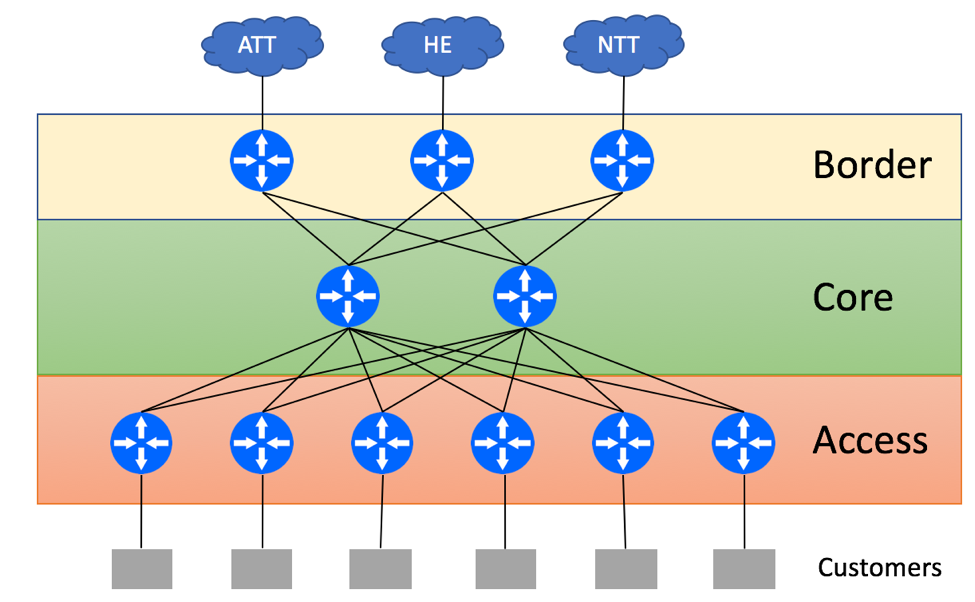
ISP has a dedicated Core Layer that aggregates connections from Border Layer devices used for external peering connectivity and Access Layer devices used for Customer connectivity. ISP is connected to three upstream providers and receives the full BGP feed from all of them. In a non-BGP-Free Core environment, Borders routers will re-advertise the routes received from external peers via IBGP to Core routers. Core routers can be used as Route-Reflectors and re-advertise full BGP view to the Access devices. If Access devices are not capable of supporting the full BGP view, you might be able to get away with advertising just the default route from the Core to Access devices. As Core routers have the full BGP view, they can find the optimal exit point for the traffic leaving the network.
Let’s review packet flow scenario with traffic originating within ISP’s customer’s network and being destined to a prefix that resides on the HE network. In our case, ISP’s Access layer does not have the full BGP view and relies on the default route received from Core routers.
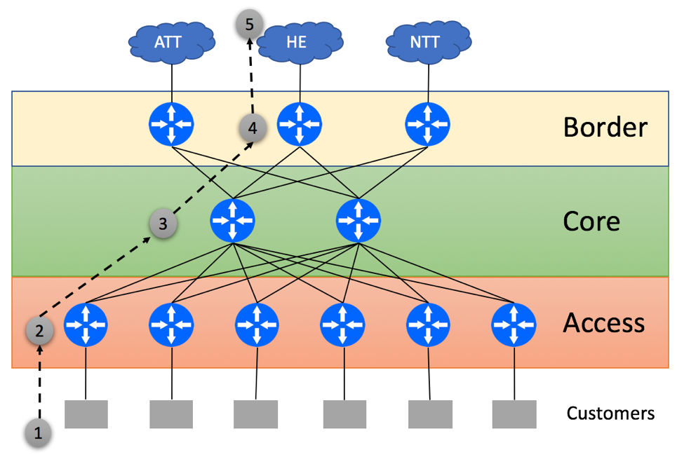
- Customer Originates the packet
- Access Layer device within ISP’s network uses the default route to send packet to one of Core routers in a round-robin fashion
- Core device does a lookup and determines that the destination on the HE’s network is best reachable via the middle border router
- Border router forwards this packet to the HE
- Server within the HE network receives the packet
Now, let’s talk about a BGP-Free Core. It is assumed that the Core has no knowledge of Customer-owned or Peer-advertised destinations and is only capable of forwarding traffic to IP destinations that belong to ISP’s internal infrastructure. Access and Border devices will have a full mesh of Tunnels (LSP’s in MPLS terminology) and will pass traffic via those tunnels.
We’ll start with the scenario where Access routers have enough RIB and FIB capacity to support the full BGP view from the Border devices.
In this case, Access layer will make optimal forwarding decisions as shown below:

- Customer Originates the packet
- Access Layer device does a lookup in its BGP tables and determines that the Middle Border router is the best gateway to reach the HE. Access Layer device will encapsulate customer-originated traffic into a tunnel and send it to the Border via one of the Core routers
- Core device receives tunneled traffic and delivers it to the intended Border router
- Middle Border Router sends packet to the HE
- Server within the HE network receives the packet
In our next scenario, Access routers are not capable of supporting the full BGP view and have to rely on the default routes, this time advertised by the Border Routers. This might lead to suboptimal traffic flow as shown below:
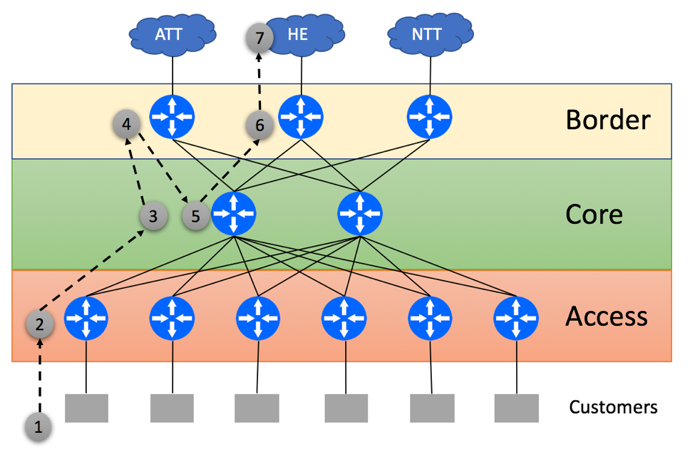
- Customer Originates the packet
- Access Layer device within ISP’s network uses the default route and tunnels packet to one of the Border routers in a round-robin fashion. It is not able to determine the best egress point, as Access device does not maintain the full BGP view
- Core device tunnels the traffic to the Border device selected by the Access Layer
- Left Border router does IP Destination lookup and determines that the optimal path to the prefix on the HE network is via the Middle Border. It Tunnels traffic to that Border
- Core router receives a tunnel-encapsulated packet and sends it to the Middle Border
- Middle Border Router sends the packet to the HE
- Server within the HE network receives the packet
Another permutation of the previous scenario is shown below. This time BGP policies on the Border routers force traffic to leave via directly connected EBGP peer, even if the better path exists:
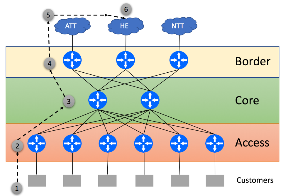
- Customer Originates the packet
- Access Layer device within ISP’s network uses the default route and tunnels packet to one of the Border routers in a round-robin fashion. It is not able to determine the best egress point, as Access device does not maintain the full BGP view
- Core device tunnels the traffic to the Border device selected by the Access Layer
- Left Border router does IP Destination lookup and selects directly connected EBGP Upstream to send the traffic
- AT&T’s network delivers the packet to HE
- Server within the HE network receives the packet
While both deployment scenarios allow for the traffic to be delivered to intended destinations, it is easy to spot that packets might need to traverse the additional hops. This will often lead to increased round-trip latency and unnecessary link utilization.
Conclusion
BGP-Free Core is a popular deployment mechanism that is employed by thousands of ISPs around the globe. It helps to save cost and improves operational stability of the network. With this being said, you should be aware of the deployment caveats highlighted above and be ready to address those in your network design.
Please refer to ‘Migrating to BGP-Free Core in Juniper Environment‘ for practical migration steps.